GD&T for Fixture Designers: Applying Tolerances to Jig Components

In precision manufacturing, the finished part is rarely better than the fixture that held it. Every clamp, locator, and drill bushing adds — or controls — a small amount of variation. In the end, that variation shows up in the inspection report.

That is why GD&T is more than a drawing language for production parts. In fact, it is a design discipline for the fixtures themselves.

This article is written for fixture designers, tooling engineers, and CNC machinists. It offers a clear way to apply GD&T to jig components. For example, it covers locating pins, rest pads, fixture plates, and — above all — drill bushings.

Why GD&T Matters in Fixture Design

A jig or fixture has one job. It must present the workpiece to the cutting tool the same way every time. For every part.

When that job is done poorly, the symptoms are familiar:

  1. Hole patterns drift between batches.
  2. Inspection rejects climb on multi-feature parts.
  3. Identical fixtures produce different results.
  4. Operators “tweak” the setup to compensate for stack-up.

In most cases, the root cause is tolerance strategy. It is rarely the machinist, the spindle, or the cutting tool. After all, if the fixture cannot hold the part the same way twice, no CNC will save the process.

GD&T fixes this directly. In short, it defines:

  1. What features control part location (datums).
  2. How related features must behave next to those datums (geometric controls).
  3. How much variation is allowed before function suffers (tolerance zones).

For a fixture designer, this means one thing. Every jig component — including every drill bushing seat — is a feature with a planned link to a known datum system.

GD&T in the Context of Fixtures

Most engineers first meet GD&T as a way to describe finished parts. In fixture design, however, the same ideas apply with a shift in purpose. Instead of describing what a part must be, GD&T sets what the fixture must promise about every part that passes through it.

Below are the controls that show up most often on a well-toleranced fixture drawing.

Datums

A datum is a perfect reference — a plane, axis, or point — from which other features are measured. In a fixture, datums are usually set by the locating surfaces themselves. For example, this includes the main face of the fixture plate, the locating pin axes, and the rest button heights.

Datums on the fixture should mirror the datum scheme of the part it holds. Otherwise, a mismatch becomes one of the most common sources of stack-up error.

True Position Precision tooling components

True position controls where a feature center may sit next to a datum reference frame. For fixture designers, true position is the main control for:

  1. Drill bushing bores
  2. Dowel pin holes
  3. Locator pin centers
  4. Mounting hole patterns

A drill bushing whose seat is even slightly off true position will guide the drill into the wrong spot on every part the fixture ever produces.

Perpendicularity

Perpendicularity controls how square a feature sits next to its datum. In fixtures, this matters for:

  1. Drill bushing axes next to the fixture face
  2. Locating pins next to the base plate
  3. Clamp contact faces next to the workpiece surface

For instance, suppose a bushing is press-fit into a hole that is not square to the fixture plate. As a result, the drill enters the workpiece at an angle. Hole position may then pass on the top surface and fail on the bottom. This is a classic angularity reject.

Parallelism

Parallelism is key for fixture plates, rest pads, and any reference surface that must stay co-planar with another. In stacked or modular fixtures, for example, parallelism between mating plates decides if the fixture holds its datum scheme after assembly.

Flatness

Flatness controls how planar a single surface is. The main locating face of a fixture, where the workpiece datum rests, almost always carries a flatness callout. In fact, a fixture base that is “flat enough” by eye can still rock a workpiece by a real amount.

Profile of a Surface

Profile tolerancing now appears more often on fixture nests and shaped supports. In particular, this is true for cast or forged workpieces. It defines a uniform tolerance zone around a perfect surface. As a result, it works well when the nest must fit a complex part shape.

Concentricity and Runout

These controls apply to rotating or coaxial features. In fixture design, they show up in spindle-mounted tooling, rotary indexers, and bushing-to-liner assemblies. For example, this matters when an inner bushing must stay coaxial with its outer liner. Concentricity is a tight and demanding control. Therefore, many designers prefer runout or position with material condition modifiers. These offer an easier path to make.

Datum Strategy for Fixture Design

A fixture’s datum strategy is the foundation of every other tolerance decision. Get it right, and downstream tolerances stay tight and inexpensive. Get it wrong, and tolerances must be tightened across the whole assembly to compensate.

Functional Datum Selection

Functional datums are those with a clear physical role in locating the part. In other words, they are not chosen for ease of inspection. Instead, they are chosen because they are the surfaces touched during machining.

The fixture’s datum scheme should match the part’s functional datum scheme. For example, if the part is dimensioned from a machined edge and two reference holes, the fixture should locate from those same features.

Primary, Secondary, and Tertiary Datums (3-2-1 Locating)

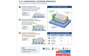
The 3-2-1 locating principle is the industry-standard way to fully hold a rigid workpiece:

  1. 3 points on the primary datum set the largest plane. As a result, this removes three degrees of freedom — one translation and two rotations.
  2. 2 points on the secondary datum set a square plane. Then, this removes two more degrees of freedom — one translation and one rotation.
  3. 1 point on the tertiary datum removes the final translation.

The result is that all six degrees of freedom are constrained without over-constraining the part. In other words, the workpiece is located, but not fought against.

A common failure mode is to add a fourth, fifth, or sixth locator “for stability.” However, this over-constrains the workpiece. It forces the part to bend against the locators. As a result, it destroys repeatability. Remember: stability comes from clamping, not from extra locators. Workholding systems for accurate manufacturing

Preventing Tolerance Stack-Up

Stack-up happens when several small tolerances build up along a chain. In fixtures, stack-up most often shows up between the fixture base, the locating pins, the bushing plate, and the drill bushing bore.

A few practices cut stack-up by a lot:

  1. Reference all key fixture features from a single primary datum where possible.
  2. Avoid chained dimensions. Instead, use baseline dimensions from the datum origin.
  3. Apply true position with the right material condition modifiers (MMC/LMC). For example, bonus tolerance can be earned through fit.
  4. Where the fixture mirrors the part’s datum scheme exactly, stack-up is reduced by design.

Applying True Position to Drill Bushings

Drill bushings are the most position-sensitive parts in any drilling jig. They guide the cutting tool directly. As a result, there is no spindle correction, no offset programming, and no probing strategy that fixes a misplaced bushing.

Hole Location Control

True position is the right control for the bore of a drill bushing seat. In short, the position callout tells the toolmaker how far the bushing center may drift in any radial direction.

In fact, position tolerance for the bushing seat must cover two stages of error:

  1. The position of the bushing bore in the fixture plate.
  2. The clearance fit between the bushing OD and its mating bore.

The drill enters the workpiece at the bushing ID. Therefore, the combined effect of these two stages sets the hole location capability of the whole jig.

Press-Fit vs. Renewable Bushings in Precision Applications

The choice between press-fit and renewable bushings is, in part, a tolerance strategy decision.

The role of drill bushings in precision machining.

Press-fit bushings (ANSI Type P and Type H) are pressed directly into a tight, toleranced hole in the jig plate. They offer the most direct, rigid path from the fixture datum to the drill. There is no liner in between, and no clearance gap. As a result, they are the standard choice for fixed, high-volume drilling jigs where the bushing is rarely changed.

Renewable bushings (ANSI Type SF slip-renewable and Type SFX locking-renewable) are used with a liner bushing (ANSI Type L or Type RL). First, the liner is press-fit into the jig plate. Then, the renewable bushing rotates or slips into the liner. As a result, operators can swap bushings between jobs — drilling, then reaming, then counterboring — through the same located hole.

The tolerance trade-off is simple. Renewable systems add one extra fit (renewable-to-liner). However, they also allow maintenance, multi-job use, and easy swap of the worn inner bushing without scrapping the fixture. For long-running production fixtures, this is almost always the better long-term choice.

Maintaining Positional Accuracy in Multi-Hole Patterns

When a single workpiece sees a pattern of drilled holes, every bushing adds to the overall position result. As a result, the combined position error of the pattern is greater than the error of any single bushing.

Two practices help:

  1. Use a composite position tolerance. This means a looser pattern-locating tolerance with a tighter hole-to-hole tolerance. In other words, it matches how the part is checked in real life.
  2. Where possible, drill the bushing pattern into the jig plate in one setup on a jig borer or precision CNC. Then ream and press the bushings in. As a result, this removes most fixture-build stack-up between bushings.

Spindle Accuracy vs. Fixture Accuracy How precision tooling improves drilling accuracy

A common belief is that a high-precision CNC will overcome a marginal jig. However, it will not. The drill is guided by the bushing, not by the spindle. So in a bushed drilling job, the spindle’s role is to deliver rotation and feed. Meanwhile, the bushing controls position. In short, fixture accuracy is the main variable.

Tolerancing Locators and Fixture Components

Not every fixture feature needs a tight tolerance. In fact, over-tolerancing raises cost without improving function. Below is a practical hierarchy for common jig components.

Features That Require Tight Tolerances

  1. Dowel pin holes — true position and squareness to the locating face. After all, these define the whole datum reference frame.
  2. Primary locating pin diameters — diameter and cylindricity. They usually need a tight fit to the part’s reference hole.
  3. Drill bushing seats — true position, squareness, and diameter tolerance to match the press-fit class of the bushing.
  4. Liner bushing seats — same as drill bushing seats. However, they should be tighter still if renewable bushings will be used.
  5. Primary locating face flatness — this sets the main datum.

Features That Can Remain Looser

  1. Clearance holes for fasteners.
  2. Cosmetic surfaces.
  3. Non-functional clamp bodies (the contact point is toleranced, not the body).
  4. Outer profiles of the fixture base, beyond what is needed for handling and mounting.

Cost vs. Precision Trade-Offs

Each extra tenth of a thousandth of tolerance has a real cost. For instance, it adds grinding time, lapping, inspection, and scrap rate during fixture build. A good designer asks one question for every tolerance: what function does this control, and what is the cost of loosening it by 50%?

If the answer is “no real effect,” then the tolerance is too tight.

Manufacturability

Tolerances that cannot be reasonably made will be ignored, waived, or burned into rework cycles. As a result, realistic tolerancing is a quiet mark of a skilled fixture designer. In short, it must match the process capability of the toolroom that will build the fixture.

Common GD&T Mistakes in Fixture Design

Most fixture problems trace back to a small set of repeated mistakes. Fortunately, watching for these during design review prevents most issues.

  1. Over-constraining the workpiece. Adding “extra” locators forces the part to bend. Remember, the 3-2-1 principle exists for a reason.
  2. Unrealistic tolerances. Specifying tolerances tighter than the toolroom can hit produces fixtures that pass on paper but fail in production.
  3. Poor datum transfer. When the fixture’s datums do not match the part’s functional datums, every inspection becomes a fight.
  4. Ignoring thermal expansion. Steel fixtures and aluminum workpieces react differently to shop temperature swings. For tight-tolerance work, this is a real error source.
  5. Wrong bushing alignment. A bushing pressed into a non-square hole drills angled holes — period.
  6. Too much stack-up. Long dimension chains between datum and feature multiply tolerance error. Fortunately, baseline dimensioning solves this.
  7. Designing for inspection rather than for the shop. It is possible to draw a fixture that is perfectly inspectable but impossible to build. The reverse is also true. In short, good fixture design balances both.

CNC Machining and Inspection Considerations

A fixture is not a one-time design event. Instead, it is a piece of production gear that wears, drifts, and eventually needs service. Therefore, GD&T strategy should plan for the fixture’s full life cycle.

CMM Inspection and Fixture Verification

The fixture itself should be checkable on the same gear used to inspect the parts it makes. Otherwise, if the fixture’s datums cannot be picked up by the CMM in a reasonable setup, the fixture cannot be verified. As a result, any drift in the fixture will be misread as a process problem.

Repeatability Studies

A new fixture should be verified with a short repeatability study before release to production. For example, run the same part through it several times. Use several machines and several operators. Then inspect the results. After that, this baseline becomes the reference for all future fixture decisions.

Gauge Correlation

If the fixture is used during in-process gauging, the gauge and CMM must agree within a fair margin. In most cases, gaps come from the gauge’s datum scheme not matching the fixture’s.

Fixture Wear Over Time

Wear is a given. The features that wear first are usually the contact surfaces. For example, this includes locator pins, rest pads, and the inner bores of drill bushings. A renewable bushing system makes this wear cheap to address. The worn bushing is simply swapped out. Meanwhile, the fixture stays in service. By contrast, a press-fit-only system makes wear far more disruptive to manage.

Replaceable Tooling Components

Designing a fixture with replaceable wear parts is one of the highest-leverage choices a fixture designer makes. For instance, renewable drill bushings, swappable rest pads, removable locator pins, and bolt-in fixture plates all extend fixture life. As a result, they also lower total cost of ownership.

Best Practices for Fixture Designers

Here is a short list of practices that produce better fixtures:

  1. Design for maintenance. Assume every wear part will be swapped out. Therefore, make swapping easy — no full teardown, no special tools, no shims.
  2. Standardize where possible. Use a consistent family of locator pins, bushings, and clamps across fixtures. As a result, this makes stocking, training, and swaps simpler.
  3. Specify renewable bushings for high-volume or multi-job jigs. In most cases, the tolerance cost is small next to the maintenance gain.
  4. Use modular fixture concepts where production volumes justify them. For example, a modular fixture base with swappable workpiece-specific tooling stays in service longer than a one-off fixture.
  5. Make inspection easy to reach. Datums should be reachable by a probe or CMM stylus without teardown.
  6. Apply MMC and LMC modifiers with care. In short, bonus tolerance is a real engineering tool — not a way to cut corners. When used right, it widens the make-able range without hurting function.
  7. Document the design intent. A fixture drawing should make clear why each tolerance is what it is. After all, the next engineer who maintains it will benefit.

Conclusion

GD&T is not paperwork. In fact, in fixture design, it is the difference between a jig that holds its accuracy over thousands of parts and one that drifts within the first production run.

A well-toleranced fixture starts with a sound datum strategy. Then it applies true position with care to drill bushings and locators. After that, it uses the right control — flatness, squareness, profile — for each feature’s real function. As a result, it accepts looser tolerances where they cost nothing. Meanwhile, it spends precision where it matters.

The outcome is a jig that makes consistent parts, accepts wear gracefully, and stays in service for the full life of the program.

Precision tooling components are a key input to that result. For example, renewable bushings, liners, and press-fit bushings — made to consistent ANSI standards — give the fixture designer reliable building blocks for a tolerance strategy that holds up in production.

Learn more about precision drill bushings and tooling components from All American Bushing.

Request a quote on drill bushings and tooling components

Common Asked Questions

What is GD&T in fixture design?

GD&T (Geometric Dimensioning and Tolerancing) in fixture design uses geometric controls to define how every locator, drill bushing, and reference surface in a jig must relate to the fixture’s datum system. For example, this includes true position, perpendicularity, parallelism, flatness, and profile. As a result, the fixture presents the workpiece to the cutting tool the same way every cycle.

Why is true position important for drill bushings?

The drill is guided by the bushing, not by the CNC spindle. Therefore, any error in the bushing’s location transfers directly into the workpiece. True position controls how much the bushing center may deviate radially from its theoretical location. In short, it is the dominant tolerance for hole-location accuracy in any drilling jig.

What is the 3-2-1 locating principle?

The 3-2-1 principle constrains a rigid workpiece using three locating points on the primary datum, two on the secondary, and one on the tertiary. As a result, this arrangement removes all six degrees of freedom without over-constraining the part. However, over-constraint forces the workpiece to deform against the locators. Then it destroys repeatability.

Should I use press-fit or renewable drill bushings?

Press-fit bushings (Type P and Type H) are ideal for dedicated, high-volume drilling jigs where the bushing is rarely changed. By contrast, renewable bushings (Type SF and Type SFX, used with Type L or Type RL liners) are better for multi-operation jigs. They also suit any fixture where the bushing will wear or need to be swapped between operations. In short, renewable systems trade a small tolerance penalty for major maintenance and lifecycle advantages.

How do I prevent tolerance stack-up in a fixture?

First, reference critical features from a single primary datum. Next, avoid chained dimensioning. Instead, use baseline dimensioning from the datum origin. Then, apply MMC or LMC modifiers where bonus tolerance can legitimately be earned. Finally, match the fixture’s datum scheme to the part’s functional datum scheme. As a result, stack-up between fixture and workpiece is minimized.

What is the most common GD&T mistake in fixture design?

The most common mistake is over-constraining the workpiece by adding extra locators “for stability.” However, this forces the part to deform against the fixture. As a result, it produces inconsistent results from cycle to cycle. Remember: stability should come from clamping, never from redundant locators.

ANSI B94.33 jig bushing tolerance chart open on engineering bench with calipers and drill bushings

Introduction

In precision machining, every micron matters. A drilled hole that drifts by even half a thousandth of an inch can put a finished part out of spec — and on a high-volume production line, that single deviation multiplies into scrap, rework, and lost time.

This is why engineers rely on jig bushing tolerance charts to specify the correct components for their fixtures. Tolerances aren’t a minor design detail. They are the foundation of repeatable, accurate drilling — and they are the reason an industry-wide standard exists.

That standard is ANSI B94.33.

This guide explains what ANSI B94.33 covers, how to read a jig bushing tolerance chart, and how engineers apply it in real CNC and fixture work.

Continue reading “Jig Bushing Tolerance Chart: ANSI B94.33 Explained for Engineers”

How to Design a Production Drill Jig: Bushing Selection, Location, and Clamping System

Introduction — Why Drill Jig Design Matters

In production machining, accuracy is not a goal — it is a requirement. When hundreds or thousands of identical parts must be drilled to the same specification, the drill jig is what makes that possible. A well-designed drill jig eliminates individual layout work on every part, enforces positional tolerances hole after hole, and dramatically reduces cycle time on the shop floor.

Poor jig design is costly in every direction. Misaligned bushings lead to out-of-tolerance holes, rejected parts, and expensive rework. Inadequate clamping allows workpiece movement during cutting, introducing chatter, tool breakage, and inconsistent hole depth. Undersized or worn bushings compromise drill guidance, turning a repeatable process into a liability.

At All American Bushing, we have supplied precision drill bushings and workholding components to manufacturers across industries for decades. This guide distills the core engineering principles behind designing a production drill jig that performs — from bushing selection and 3-2-1 locating to clamping system design and jig validation.

What Is a Drill Jig?

A drill jig is a workholding device that guides a cutting tool — typically a drill, reamer, or countersink — to a precise location on a workpiece. Unlike a fixture, which only holds a part in a fixed position, a jig contains hardened drill bushings that physically guide the tool along its cutting axis.

  1. Fixture: Locates and clamps the workpiece but provides no tool guidance. Used with CNC machines that rely on programmed coordinates.
  2. Jig: Both locates the workpiece and guides the tool through hardened bushings, making it ideal for manual drill press operations and high-volume production where dedicated tooling is more economical than CNC time.

Drill jigs are common in automotive, aerospace, electronics, and general manufacturing wherever repeatable hole patterns must be produced efficiently and to tight tolerances.

Core Drill Jig Components

A production drill jig is an assembly of purpose-engineered components. Understanding each element is essential before beginning the design process.


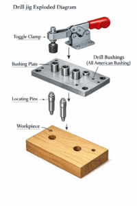
Drill jig exploded diagram showing bushing plate, toggle clamp, locating pins, and workpiece — All American BushingDrill Bushings

Drill bushings are hardened, precision-ground cylinders inserted into the jig body to guide the cutting tool. All American Bushing manufactures three primary types:

  1. Press-fit (fixed) bushings — Permanently pressed into the bushing plate. Best for long production runs where the bushing diameter never changes. Available in standard head and headless configurations.
  2. Slip-fixed bushings (liner + slip bushing) — A hardened liner is pressed permanently into the plate; a slip bushing is inserted into the liner and can be replaced or swapped for a different tool diameter without disturbing the jig. Ideal when a hole requires multiple operations (drill, ream, countersink) in sequence.
  3. Renewable bushings — Designed for high-wear applications. They lock in place during use and can be quickly exchanged when worn, extending jig life significantly.

Browse our complete line of drill bushings.

Bushing Plates

The bushing plate is the structural element that holds the bushings in correct relationship to one another and to the workpiece. It is typically made from tool steel or hardened steel plate. Plate thickness, bushing spacing, and chip clearance between the bushing face and workpiece are all critical design parameters.

Locating Pins

Locating pins establish the datum references that repeatably position the workpiece in the jig. They are machined to close tolerances and engage existing features on the part — typically a machined hole, edge, or slot — to eliminate positional degrees of freedom.

Rest Pads and Buttons

Rest pads (or rest buttons) support the workpiece at defined contact points, preventing deflection under clamping or cutting forces. They are hardened and ground to maintain a consistent reference surface throughout the life of the jig.

Toggle Clamps

Toggle clamps are the most common clamping mechanism in drill jig design. They apply consistent clamping force quickly, allow single-handed operation, and are available in horizontal, vertical, and push-pull configurations. Proper toggle clamp selection depends on required holding force, available real estate on the jig body, and the direction of cutting forces.

Explore our full range of jig and fixture components.

Step-by-Step: How to Design a Production Drill Jig

Step 1: Define the Workpiece and Tolerances

Before anything is drawn, gather the complete workpiece print. Identify the holes to be drilled (diameter, depth, finish), positional tolerances per GD&T (true position, perpendicularity), part material and hardness, and expected production volume.

Engineering tip: Tighter hole tolerances generally require slip-fixed bushings with a separate reaming operation rather than drilling alone. Define your tolerance stack-up at this stage to avoid redesigning the jig later.

Common mistake to avoid: Designing to nominal dimensions without accounting for GD&T callouts. A hole with a ±0.005″ positional tolerance requires a fundamentally different jig design than one with ±0.001″.

Reference: ASME Y14.5 — Dimensioning and Tolerancing for GD&T interpretation.

Step 2: Select the Correct Drill Bushings

Bushing selection drives hole accuracy. Key parameters to specify:

  1. Inside diameter (ID): Match to drill diameter with an H7 bore tolerance for proper running fit. A bushing ID too large allows the drill to wander; too tight creates friction and heat.
  2. Outside diameter (OD) and fit: Press-fit bushings are held in the plate with an interference fit (P6 press fit per ANSI B94.33). Confirm the plate material and thickness can sustain press force without distortion.
  3. Bushing length: Longer bushings provide better guidance but increase chip clearance requirements. Minimum bushing length is typically 1× to 1.5× the drill diameter.
  4. Material: Standard drill bushings are case-hardened steel. For abrasive materials or high-cycle applications, consider carbide-lined or solid carbide bushings.

Engineering tip: For holes requiring both drilling and reaming, specify a liner bushing pressed permanently into the plate, then use dedicated slip bushings for the drill and ream diameters separately.

Common mistake to avoid: Choosing bushing ID based on nominal drill diameter without applying the correct bore tolerance, which produces excessive clearance over time and allows drill deflection.

See our drill bushing selection guide for standard ANSI sizes and fit recommendations.

Step 3: Apply the 3-2-1 Locating Principle

The 3-2-1 principle is the foundational rule of workpiece location in jig and fixture design. A rigid body in free space has six degrees of freedom: three translational (X, Y, Z) and three rotational (Rx, Ry, Rz). To fully and uniquely locate a workpiece, all six must be constrained.


3-2-1 workpiece location principle diagram for jig and fixture design — locating pins and rest buttons — All American Bushing

3 points on the primary datum plane — constrains Z translation and Rx, Ry rotations

  1. 2 points on the secondary datum plane — constrains Y translation and Rz rotation
  2. 1 point on the tertiary datum plane — constrains X translation

Engineering tip: The 3 primary datum points should be spread as far apart as possible on the largest flat surface of the part to maximize angular stability. Narrow contact point spacing amplifies angular error.

Common mistake to avoid: Using 4 or more points on the primary datum (over-constraining). On a non-perfectly flat part, a 4-point contact rocks unpredictably. Three points always form a stable plane.

Step 4: Design Locating Pins and Supports

With the 3-2-1 scheme defined, select and position the physical locating elements:

  1. Solid locating pins engage the primary datum hole or reference edge using a tight sliding fit (H7/g6).
  2. Diamond (relieved) pins engage a second datum hole. The diamond shape relieves the over-constrained direction, accommodating hole-to-hole distance variation without binding.
  3. Rest pads support the three primary datum points and should be positioned directly below clamping points to prevent part deflection.

Engineering tip: Place locating pins in the order the part will be loaded — the primary pin first, the diamond pin second. This makes loading intuitive and reduces operator error.

Common mistake to avoid: Positioning rest pads and clamps asymmetrically so that clamping force tilts the workpiece off the primary datum. The clamping load must act directly over (or as close as possible to) a rest pad.

Step 5: Choose the Clamping System

Clamping holds the workpiece against its locating points throughout the cutting operation. The clamping system must apply sufficient force to resist cutting thrust, avoid workpiece distortion, allow fast repeatable loading and unloading, and not obstruct tool access or chip evacuation.

3-2-1 workpiece location principle diagram for jig and fixture design — locating pins and rest buttons — All American Bushing


Toggle clamps are the standard for production drill jigs because they deliver consistent force at a defined closed position. Specify clamp holding capacity at 2× to 3× the expected axial cutting force (drill thrust). Direct clamping over the support point is always preferred over strap clamping across unsupported spans.

Engineering tip: Orient the clamping force vector perpendicular to the primary datum surface and directly over a rest pad. This prevents rocking and ensures the part seats fully before the drill engages.

Common mistake to avoid: Using a single central clamp on a large part. Cutting forces at a remote location can rotate the part about the clamp point. Use two clamps bracketing the drilling zone when in doubt.

Step 6: Design the Bushing Plate and Alignment

The bushing plate must position drill bushings accurately relative to the locating datums. Key design considerations:

  1. Chip clearance: Maintain a gap of 1× to 1.5× the drill diameter between the bushing face and workpiece surface.
  2. Plate thickness: Must provide at least 1× bushing OD of plate engagement to fully support the bushing.
  3. Alignment: The bushing plate must be located on the jig body with two dowel pins to ensure repeatable positioning if removed for bushing replacement.
  4. Hardening: Bushing plates for production use should be hardened and ground after machining to maintain flatness and resist wear.

Engineering tip: Design the bushing plate as a separate, removable sub-assembly. When bushings wear out after thousands of cycles, replacing the plate rather than the entire jig is far more economical.

Common mistake to avoid: Relying on fastener holes alone to locate the bushing plate. Bolts allow slight rotational shift under repeated clamping loads. Always use dowel pins for positive location.

Step 7: Validate and Test the Jig

Before committing to production, validate the jig systematically:

  1. Gage the locating features — Verify rest pad heights and pin locations against the jig drawing using a CMM or height gage.
  2. Load and unload the workpiece 20+ times — Confirm the part seats consistently and the locating pins engage without forcing.
  3. Run a pilot lot — Drill 5 to 10 parts and inspect hole position on a CMM or optical comparator.
  4. Check bushing wear — After the pilot lot, measure bushing IDs against nominal. Excessive wear indicates an incorrect fit or inadequate lubrication protocol.
  5. Document the baseline — Record initial measurements so wear trends can be tracked over the production life of the jig.

Engineering tip: Include a jig setup sheet with the first-article inspection report. Operators should have a visual reference showing correct part orientation and clamping sequence.

Common mistake to avoid: Skipping the pilot lot and going straight to full production. Problems discovered at 5 parts cost far less to fix than problems discovered at 500.

Drill Bushing Selection Guide

Selecting the right bushing type comes down to three factors: operation sequence, production volume, and wear tolerance.

Bushing Type Best For Replacement Method
Press-fit (fixed) Single-operation, high volume Requires plate rework
Slip-fixed (liner system) Multi-operation (drill + ream) Slip bushing only
Renewable Extreme wear / abrasive materials Field swap, no downtime

Standard ANSI bushings are manufactured from case-hardened tool steel (Rc 60–65 on the ID). For drilling aluminum, titanium, or composites where chip adhesion is a concern, consider TiN-coated or carbide bushings. Per ANSI B94.33, press-fit bushings use a P6 interference fit — confirm the plate bore is reamed after hardening to maintain this tolerance.

View our drill bushing catalog.

3-2-1 Locating Principle Explained

The elegance of 3-2-1 is that it uses the minimum necessary constraints to achieve full location — no more, no less. Over-constrained systems introduce indeterminate contact, meaning position varies part to part based on geometric imperfections in the workpiece surface.

In practice, the three datum planes in 3-2-1 correspond directly to the GD&T datum reference frame (DRF) on the part drawing. The primary datum is established first and takes priority; the secondary datum must be square to the primary; the tertiary datum must be square to both. For prismatic parts, three rest buttons on the bottom face, two locating pins on one side edge, and one pin or stop on the end face is the textbook implementation.

Clamping System Design

The most common clamping failures in drill jig design are insufficient clamping force and incorrect force direction. Clamping force must act toward a supported datum surface, not across an unsupported span. For thin-walled or compliant workpieces, distribute clamping force over larger contact areas using strap clamps with soft pads, or use more clamp points at lower individual force.

For high-cycle production (several hundred parts per day or more), pneumatic toggle clamps reduce operator fatigue and improve cycle consistency. They can be interlocked with the spindle to prevent drilling unless the clamp is fully seated — an important safety and quality control feature.

Ready to source clamping and workholding components? Contact All American Bushing.

Frequently Asked Questions — Drill Jig Design

What is a drill jig?

A drill jig is a workholding device that both locates a workpiece in a fixed position and guides a drill (or other cutting tool) through hardened bushings to a precise location. Unlike a fixture, a jig provides physical tool guidance, making it ideal for repeatable hole patterns in high-volume production.

What is the 3-2-1 rule in jig and fixture design?

The 3-2-1 rule is a fundamental principle of workpiece location that eliminates all six degrees of freedom using the minimum number of contact points: 3 on the primary datum plane, 2 on the secondary, and 1 on the tertiary. This prevents over-constraint and ensures consistent part positioning every cycle.

How do you choose the right drill bushing?

Start with the drill diameter and required tolerance. For single-operation holes, press-fit (fixed) bushings are standard. For multi-step operations (drill + ream), use a liner and slip bushing system. Match the bushing ID to the drill with an H7 bore tolerance and use the ANSI P6 press fit for the OD-to-plate engagement.

What is the difference between a jig and a fixture?

A fixture only locates and holds the workpiece; it does not guide the cutting tool. A jig locates and holds the workpiece and guides the tool through hardened bushings. CNC machining uses fixtures with programmed coordinates; manual and semi-automatic drilling uses jigs for physical tool guidance.

How much chip clearance should a drill jig have?

A gap of 1× to 1.5× the drill diameter between the bushing face and the workpiece surface is the standard recommendation. This allows chips to exit without packing while keeping the drill under bushing guidance as early as possible.

When should I use renewable bushings instead of press-fit?

Use renewable bushings when drilling abrasive materials such as composites or cast iron, in very high-volume operations where bushing wear is rapid, or when minimizing jig downtime for bushing replacement is a production priority.

Ready to Source Your Drill Bushings?

Designing a production drill jig starts with the right components — and that starts with precision bushings manufactured to ANSI standards. All American Bushing supplies press-fit, slip-fixed, and renewable drill bushings in standard and custom sizes, with fast lead times for production tooling programs.

➡ Request a Quote for Drill Bushings

➡ Contact Our Engineering Team for Jig Design Support

Drill Bushing Types Guide: ANSI P, H, SF, PM & More

Choosing the wrong drill bushing can ruin a part, slow down production, and cost your shop real money.

Whether you’re building a new drill jig or upgrading an existing fixture, understanding drill bushing types is one of the most important decisions you’ll make. The right bushing keeps your drill on target, hole after hole, shift after shift.

In this guide, we cover all major ANSI drill bushing types — P, H, SF, PM, SFX, and HM — so you can select the right one with confidence. You’ll also get a full breakdown of press fit vs renewable bushings and a practical selection guide for your specific production needs.

Let’s get started.

Continue reading “Drill Bushing Types Guide | All American Bushing”

Workholding Systems for Accurate Manufacturing

Modern manufacturing requires precision, consistency, and efficiency. Machines can cut and shape materials with incredible accuracy, but they still depend on proper workholding and tooling components to perform reliably.

Manufacturers use workholding systems to secure parts and guide tools during machining operations. These systems often combine clamping components, drill bushings, and alignment tooling to create stable and repeatable production processes.

Reliable solutions from company like  All American Bushing help manufacturers improve accuracy and maintain consistent production quality across many industries.

This article explains what workholding system is, how toggle clamps and drill bushings function in manufacturing systems, and why combining these tooling components improves overall production performance.

Continue reading “Workholding Systems for Accurate Manufacturing”

What Are Drill Bushings? Essential Components for Precision Machining

Precision plays a key role in modern manufacturing. Machines must produce parts with exact dimensions and consistent quality. To achieve this, manufacturers rely on many small but important tooling components. One of these components is the drill bushing.

Drill bushings guide cutting tools during drilling operations. As a result, they help ensure accurate hole placement and consistent machining results. Many industries use them in jigs, fixtures, and drilling systems.

Manufacturers often rely on trusted suppliers such as All American Bushing to provide durable and precise drill bushings for industrial applications.

Continue reading “What Are Drill Bushings? Essential Components for Precision Machining”

In modern manufacturing, precision and reliability depend not only on advanced machines but also on the quality of the tooling components used throughout the production process. From CNC machining centers to assembly lines, small but essential components such as clamps, bushings, and fixture elements help manufacturers maintain accuracy, safety, and efficiency.

Two well-recognized names in the industrial tooling world are Kakuta and All American Bushing. Each brand specializes in critical tooling components that support manufacturers, engineers, and production teams across many industries.

While Kakuta is widely known for its precision toggle clamps and clamping solutions, All American Bushing has built a strong reputation for drill bushings and tooling components used in precision machining and fixture design.

Together, these brands represent reliability, engineering precision, and long-term performance in demanding manufacturing environments.

Continue reading “Introduction to All American Bushing: Trusted Industrial Tooling Brands”