
Introduction
In precision machining, every micron matters. A drilled hole that drifts by even half a thousandth of an inch can put a finished part out of spec — and on a high-volume production line, that single deviation multiplies into scrap, rework, and lost time.
This is why engineers rely on jig bushing tolerance charts to specify the correct components for their fixtures. Tolerances aren’t a minor design detail. They are the foundation of repeatable, accurate drilling — and they are the reason an industry-wide standard exists.
That standard is ANSI B94.33.
This guide explains what ANSI B94.33 covers, how to read a jig bushing tolerance chart, and how engineers apply it in real CNC and fixture work.
What Is ANSI B94.33?
ANSI B94.33 is the American National Standard that defines sizes, types, tolerances, and identification of jig bushings tolerance charts and the locking devices that secure them.
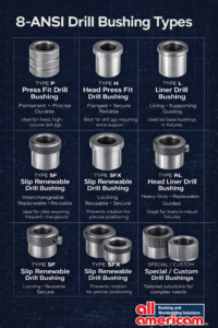
It governs the dimensional rules for the four core bushing types used across industrial manufacturing:
- Press-fit drill bushings (Type P, Type H)
- Liner bushings (Type L, Type RL)
- Slip renewable bushings (Type SF, Type SFX)
- Locking and head-locking bushings (Type DG, Type HL, Type HM)
The standard ensures that a 1/2″ press-fit bushing manufactured in one shop fits the same jig plate as a 1/2″ press-fit bushing from another supplier — provided both are made to ANSI B94.33. That interoperability is what makes precision tooling scalable across plants, partners, and product lines.
For engineers, the practical takeaway is simple: when a print calls out an ANSI B94.33 bushing, you know exactly what dimensional behaviour to expect.
Understanding Jig Bushing Tolerances
A jig bushing has two critical dimensions, and ANSI B94.33 controls both.
Inside Diameter (ID) Tolerance
The ID is the bore that guides the cutting tool — the drill, reamer, or tap. Its tolerance determines how tightly the tool is held in alignment.
ANSI B94.33 specifies different ID tolerances depending on whether the bushing is intended for a drill or a reamer, because reamers require a slightly looser fit to avoid binding.
Standard ID tolerances per ANSI B94.33 (for drill sizes):
| Bushing Bore Range | ID Tolerance Over Nominal |
|---|---|
| .0135″ – .2500″ | +.0001″ / +.0004″ |
| Over .2500″ – .7500″ | +.0001″ / +.0005″ |
| Over .7500″ – 1.500″ | +.0002″ / +.0006″ |
| Over 1.5000″ – 1.8750″ | +.0003″ / +.0007″ |
Standard ID tolerances per ANSI B94.33 (for reamer sizes):
| Bushing Bore Range | ID Tolerance Over Nominal |
|---|---|
| .0135″ – .2500″ | +.0005″ / +.0008″ |
| Over .2500″ – 1.0000″ | +.0006″ / +.0010″ |
| Over 1.0000″ | +.0008″ / +.0012″ |
Note that the ID is always plus-tolerance — never undersized — because the tool must enter the bushing freely.
Outside Diameter (OD) Tolerance
The OD controls how the bushing seats in the jig plate or liner. ANSI B94.33 defines two distinct OD tolerance bands:
- Press-fit OD — slightly oversized to create interference with the jig plate hole
- Slip-fit OD — slightly undersized so the bushing can be inserted and removed by hand or with a locking screw
Example OD tolerances (selected sizes):
| Nominal OD | Press-Fit OD | Slip-Fit OD | Recommended Jig Bore |
|---|---|---|---|
| 1/4″ | .2516 – .2513 | .2500 – .2498 | .2510 – .2507 |
| 1/2″ | .5017 – .5014 | .5000 – .4998 | .5010 – .5007 |
| 1″ | 1.0018 – 1.0015 | 1.0000 – .9998 | 1.0010 – 1.0007 |
| 1-1/2″ | 1.5022 – 1.5018 | 1.5000 – 1.4997 | 1.5010 – 1.5007 |
The interference between press-fit OD and the jig bore typically falls in the .0005″ – .0008″ range — enough to retain the bushing reliably without distorting the jig plate.
Fit Types: Clearance vs. Interference
ANSI B94.33 effectively defines two fit categories:
- Interference fit — used for press-fit bushings (Type P, H) and liner bushings (Type L, RL). The OD is larger than the host hole, requiring an arbor press for installation.
- Clearance fit — used for slip renewable bushings (Type SF, SFX). The OD is slightly smaller than the liner ID, allowing quick changeover.
Choosing the wrong fit is one of the most common — and most costly — design errors in fixture tooling.
Concentricity
ANSI B94.33 also controls concentricity between ID and OD. For ground bushings, concentricity is held to .0003″ TIR for IDs from 1/8″ to 1/2″, and .0005″ TIR for sizes above or below that range. This ensures the cutting tool is guided coaxially with the bushing’s seating surface — the foundation of straight, on-location holes.
Why Tolerances Matter in Real Applications
Specifying the correct tolerance is not a paperwork exercise. It directly affects four production outcomes:
1. Hole position accuracy. A bushing held to ANSI B94.33 ID tolerance can guide a drill to within a few thousandths of true position. A bushing made loose — or worn beyond spec — lets the drill wander.
2. Tool life. Excess clearance between drill and bushing ID causes the drill to flex during entry. That flex shows up as accelerated cutting-edge wear and shorter tool life.
3. Repeatability across the production run. Tight, consistent tolerances mean the 1,000th hole drilled in a fixture matches the 1st. Loose tolerances mean drift.
4. Surface finish and burr formation. A drill guided cleanly produces a cleaner exit. A drill that walks produces tear-out, burrs, and reamer chatter on secondary operations.
When engineers report drilling problems on a production line, the bushing tolerance is often where the investigation should start.
How Engineers Use Tolerance Charts
Tolerance charts are not reference material for archive shelves. They are working documents used at three points in the design and build cycle:
During jig design. Engineers select bushing OD class (press fit vs. slip) based on whether the bushing will be permanent or replaceable. The corresponding jig bore hole size is read directly from the chart and called out on the fixture print.
During fixture machining. Toolmakers reference the chart to set reamer sizes for installation holes. ANSI B94.33 specifies a jig bore hole .0007″ to .0010″ smaller than the press-fit OD on most sizes — which produces the recommended interference automatically when a standard chucking reamer is used.
During CNC operation planning. Process engineers specify drill or reamer sizes that match the bushing ID. Using the wrong tool size for a given bushing ID is a frequent source of out-of-spec parts on outsourced or transferred jobs.
A tolerance chart printed at the bench or saved in the engineering drive turns ANSI B94.33 into a working reference instead of a buried specification.
Common Mistakes to Avoid
Even experienced engineers run into the same recurring pitfalls. Watch for these:
- Selecting the wrong fit type. Specifying a press-fit OD for an application that requires frequent changeover — or a slip-fit OD without a liner — is a top cause of tooling failure.
- Ignoring tolerance stack-up. When multiple bushings are used in a single fixture, individual tolerances accumulate. Engineers should verify that the worst-case stack still meets part tolerance.
- Using a drill bushing for reaming. Drill-size IDs are too tight for reamers. Always specify reamer-size bushings (looser ID tolerance) when the operation requires it.
- Over-pressing the bushing. Excessive interference distorts the jig plate and closes the bushing ID — a violation of the very tolerances ANSI B94.33 was designed to protect.
- Skipping the jig bore. Installing a bushing into a twist-drilled hole rarely produces a true round seat. ANSI tolerances assume a reamed or jig-bored installation hole.
Download the Jig Bushing Tolerance Chart
To make ANSI B94.33 tolerances easy to reference at the bench or design desk, All American Bushing has compiled a printable, engineer-ready PDF chart.
It includes:
- Standard ID tolerances for drill and reamer sizes
- Press-fit and slip-fit OD tolerances by nominal size
- Recommended jig bore hole sizes
- Concentricity and interference guidelines
- A quick reference for fit selection
Download the ANSI B94.33 Jig Bushing Tolerance Chart (PDF) →
Conclusion
ANSI B94.33 exists for a reason. It turns a precision-driven discipline — jig and fixture tooling — into a predictable, repeatable engineering practice. When the bushing on your print conforms to the standard, every downstream decision (fixture machining, tool selection, production planning) becomes simpler and more reliable.
For engineers building or sourcing jigs and fixtures, the tolerance chart is the single most useful working document in the standard. Keep it close, apply it consistently, and the precision follows.
For more on bushing types and selection, explore our guides on drill bushings, tooling components, and our overview of what drill bushings are and how they work.